A Proof-of-Concept Comparison of Azure Kinect and Smartphone-based OpenCap for Driving Musculoskeletal Simulations: A Unified Framework with Foot-Ground Contact Modeling
1School of Construction Machinery, Chang’an University, Xi’an 710064, China
2Department of Obstetrics and Gynaecology, Shenzhen University General Hospital, Shenzhen 518000, China
3State Key Laboratory for Manufacturing System Engineering, School of Mechanical Engineering, Xi’an Jiaotong University, Xi’an 710054, China
4Honghui Hospital, Xi’an Jiaotong University, Xi’an 710054, China
5Department of Arthroplasty Surgery, The Second Affiliated Hospital of Inner Mongolia Medical University, Hohhot 010020, China
6Department of Rehabilitation Medicine, Shenzhen University General Hospital, Shenzhen 518055, China
7Guangdong-Hong Kong-Macao Joint Laboratory of Human-Machine Intelligence-Synergy Systems, Shenzhen Institutes of Advanced Technology (SIAT), Chinese Academy of Sciences (CAS), Shenzhen 518055, China
*Correspondence to: Dr. Zhenxian Chen,Senior Engineer, School of Construction Machinery, Chang’an University, Xi’an,710064, China. E-mail: zhenxian_chen@yeah.net; Dr. Yinghu Peng, Associate Professor, Guangdong-Hong Kong-Macao Joint Laboratory of Human-Machine Intelligence-Synergy Systems, Shenzhen Institutes of Advanced Technology (SIAT), Chinese Academy of Sciences (CAS), Shenzhen 518055, China. E-mail: yh.peng@siat.ac.cn
Received: January 7 2026; Revised: March 23 2026; Accepted: March 29 2026; Published Online: April 10 2026
Cite this paper:
Gao Q, Wang Y, Dang X et al. A Proof-of-Concept Comparison of Azure Kinect and Smartphone-based OpenCap for Driving Musculoskeletal Simulations: A Unified Framework with Foot-Ground Contact Modeling. BIO Integration 2026; 7: 1–11.
DOI: 10.15212/bioi-2026-0007. Available at: https://bio-integration.org/
Download citation
© 2026 The Authors. This is an open access article distributed under the terms of the Creative Commons Attribution License (https://creativecommons.org/licenses/by/4.0/). See https://bio-integration.org/copyright-and-permissions/
Abstract
Background: Marker-based motion capture remains the gold standard for deriving lower-limb kinematics and kinetics, but its high cost, lengthy setup time, and large space requirements limit its widespread use. Markerless technologies, such as depth camera systems (e.g., Azure Kinect) and emerging smartphone-based pipelines (e.g., OpenCap), promise laboratory-grade motion capture without markers. However, the effects of their capture data on musculoskeletal multibody dynamics simulation outcomes remain insufficiently understood.
Methods: This study was aimed at developing a single lower-limb musculoskeletal model simultaneously driven by two markerless motion capture inputs (Azure Kinect and OpenCap), and benchmarking the resulting joint angles, ground-reaction forces, and joint contact forces against synchronous Vicon recordings. In gait trials, movements were simultaneously recorded with Azure Kinect, OpenCap, and a Vicon motion capture system. The collected data were processed and used as inputs to construct the musculoskeletal model, which was then combined with a foot-ground contact model to compute lower-limb joint angles, ground reaction forces (GRFs), and joint contact forces.
Results: The OpenCap-based model showed strong agreement with the Vicon-referenced model (ρρ > 0.73) in hip flexion-extension (FE), knee FE, and ankle FE, with a root mean square error (RMSE) of 4.04° to 7.66°, Sprague and Geers magnitude error (M) of −0.25 to −0.10, phase error (P) of 0.08 to 0.25, and composite error (C) of 0.16 to 0.39. Additionally, strong correlations (ρ > 0.77) in hip contact force, knee contact force, medial knee contact force, and ankle contact force were observed between OpenCap and Vicon, with an RMSE of 0.26 to 0.90 Body Weight (BW), M of −0.03 to 0.13, P of 0.05 to 0.08, and C of 0.08 to 0.17.
Conclusions: Overall, under the study conditions, the smartphone-based OpenCap preliminarily showed accuracy as a potential alternative to marker-based systems for estimating lower-limb biomechanics. However, given the small sample size and tasks restricted to walking, it is currently primarily suited for research settings or initial screening, rather than high-precision clinical diagnosis. Further studies in larger, more diverse cohorts and validation across dynamic activities are required to confirm and extend its applicability.
Keywords
Foot-ground contact, kinematics, kinetics, lower-limb biomechanics, markerless motion capture, musculoskeletal multibody dynamics.
Introduction
Kinematic and kinetic data for the human lower-limb joints are fundamental for clinical research on pathogenesis [1–4], assessment of surgical failure mechanisms, and development of rehabilitation strategies and therapeutic interventions [5]. Nevertheless, directly measuring the biomechanical characteristics of patients’ lower limbs remains challenging. Although technologies such as instrumented joint implants for measuring joint force [6], the EOS™ imaging system [7], and dual fluoroscopic imaging analysis [8] have facilitated the assessment of lower-limb joint motion, these approaches are invasive, costly, or limited by small sample sizes, thereby restricting their applicability to larger and more diverse populations [6]. Musculoskeletal multibody dynamics simulation offers a non-invasive method to precisely assess joint motion, contact forces, and moments, as well as forces exerted by muscles and ligaments during functional activities [9–11]. It has been widely used in research in motion analysis [12], surgical alignment planning [13], and implant design [14].
Currently, the predominant approach in musculoskeletal multibody dynamics simulations uses inverse kinematics methods, which require motion capture data as input to operate the musculoskeletal models [10]. Such motion capture data are generally acquired with marker-based systems, including Vicon [15] and Qualisys [16], which comprise six to twelve infrared cameras for tracking marker trajectories and two to four force plates for measuring GRFs. However, marker-based motion capture systems encounter several challenges, including prolonged data acquisition, marker occlusion, substantial equipment costs, and a need for dedicated laboratory facilities [17–19]. In healthcare facilities with limited physical space, deploying marker-based motion capture systems for clinical diagnosis and research poses substantial challenges. Recently, advancements in markerless motion capture technology have facilitated the use of consumer-grade imaging systems, including RGB-D camera-based systems such as Azure Kinect [18–20] and smartphone video-based platforms such as OpenCap [21], in the study of human motion. These developments provide new avenues for rapid motion data collection and musculoskeletal model-based analysis.
Although markerless motion capture methods have been used to evaluate lower-limb joint kinematics [21], the lack of force plates restricts their effectiveness in forecasting lower-limb joint kinetics [22, 23]. Foot-ground contact modeling [24–26] has facilitated the estimation of lower-limb joint mechanics and GRF from kinematic data alone. Ripic et al. [27] have used the Azure Kinect to facilitate musculoskeletal multibody simulations to derive GRFs and joint moments during gait analysis. Albert et al. [18] have found that Azure Kinect has better accuracy for spatial gait parameters, but shows no significant differences for temporal parameters compared with Kinect v2, in gait analysis. Kakavand et al. [12] have observed very strong agreement for sagittal plane joint angles and moments in a comparison of the OpenCap system with Vicon for quantifying lower-limb kinematics and kinetics during cycling at various speeds and resistances. Horsak et al. [28] have used the OpenCap system to assess lower-limb joint kinematics during both healthy and pathological gait, which achieved moderate accuracy with errors exceeding clinically acceptable thresholds in certain gait patterns. Although these investigations have advanced markerless motion capture-based musculoskeletal multibody simulation workflows [19, 27, 29], whether the OpenCap system can achieve closer agreement than the Azure Kinect system in estimating joint kinematics and kinetics within a unified musculoskeletal simulation framework remains unclear.
This study was aimed at comparing two markerless motion capture systems for estimating lower-limb joint kinematics and kinetics, by using synchronous Vicon recordings as the reference standard. Gait data from all systems were processed within a unified lower-limb musculoskeletal model incorporating foot-ground contact to evaluate hip, knee, and ankle joint angles, as well as joint contact forces.
Methods
Participants
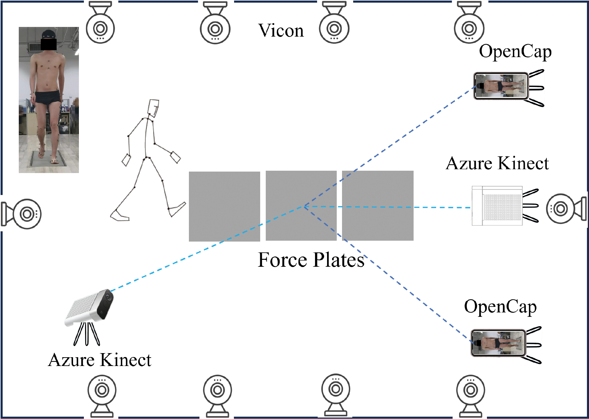
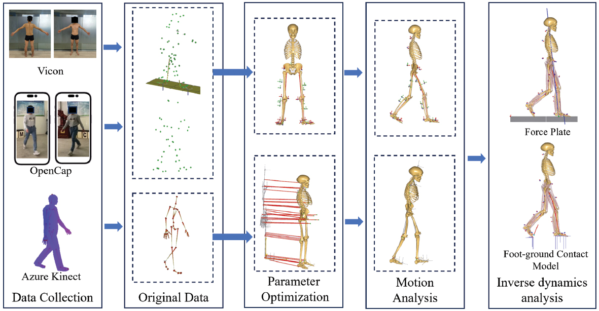
This study involved five healthy young male participants (mean age: 24 ± 5 years; mean height: 1.70 ± 0.20 m; mean body mass: 75 ± 25 kg). The inclusion criteria were as follows: (1) age between 18 and 35 years; (2) absence of major chronic diseases such as heart disease and diabetes; and (3) no use of long-term medication. The study was approved by the Ethics Committee of Honghui Hospital (No. 202407002), and all participants provided written informed consent before data collection. After providing informed consent, participants conducted gait trials at a self-selected speed, during which data were concurrently collected with the Vicon, Azure Kinect, and OpenCap motion capture systems (Figure 1).
Figure 1 Schematic of simultaneous collection by Vicon, Azure Kinect, and OpenCap capture.
Vicon motion capture system
Marker-based motion capture was performed with the Vicon motion capture system (Vicon, Oxford Metrics Ltd., Oxford, UK), consisting of ten cameras operating at 100 Hz. Three AMTI Gen5/Optima force plates (AMTI, Watertown, MA, USA) embedded in the laboratory floor were used to measure GRFs and moments at 1000 Hz. After reflective markers were placed on the participants’ entire bodies, they assumed a T-pose with both arms abducted and maintained it for 3 seconds on the force plates. This procedure was conducted to collect static data and develop rigid-body models. Subsequently, participants walked at normal speed with a single foot contacting the force plate, and the recorded marker trajectories and force plate data were saved in C3D format.
Azure Kinect motion capture system
Human kinematic data were acquired with two Azure Kinect depth cameras (Microsoft Corp., Redmond, WA) at 30 fps with iPi Recorder v.4.6.6.95 software (iPi Soft, LLC, Moscow, Russia). The depth cameras were arranged at an inter-camera angle of 120°, with the front camera located 4 m from the participant, mounted at a height of 0.75 m, and ensuring complete body visibility in each view [17]. At the beginning of the experiment, participants maintained a T-pose for 3 seconds to initialize body tracking during the depth data post-processing stage. The motion data captured by the two Kinect sensors were tracked in iPi Mocap Studio 4 software (iPi Soft, LLC, Moscow, Russia) and saved in BVH format, which includes trajectories of 19 skeletal joint centers. The BVH files were then converted to TXT files suitable for driving simulations in AnyBody with MATLAB (v. R2022b, The MathWorks Inc., Natick, MA, USA) [19].
OpenCap motion capture system
The OpenCap motion capture system used two iPhone 12 smartphones (Apple Inc., California, USA) to record participants’ gait. According to guidance from the web application, a checkerboard was placed within the field of view of the iOS devices. The two smartphones were mounted at a height of 1.5 m and positioned with an inter-camera angle of 90°, and OpenCap automatically computed the extrinsic parameters from a single image of the checkerboard for calibration [21]. After calibration, the two smartphones were synchronized for video recording via the web application. Videos were recorded at 60 Hz with a resolution of 720 × 1280 pixels. A video-based pose detection algorithm [21, 30] was then applied to extract 2D keypoint positions, and temporal synchronization was achieved with cross-correlation of keypoint velocities across videos [30]. OpenCap triangulated the synchronized 2D keypoint positions to obtain 3D coordinates, which were then refined with a long short-term memory network to estimate the 3D positions of anatomical landmarks. The coordinates of 43 anatomical markers were exported in TRC format and subsequently converted into C3D files in ezc3d software [31].
Musculoskeletal models
The musculoskeletal simulation workflow comprised three sequential steps. First, the lower-limb musculoskeletal model provided by the AnyBody Modeling System (v.7.4.4, AnyBody Technology, Aalborg, Denmark) was individualized according to each participant’s specific parameters, including body height, body weight, and anatomical markers on the skin. Second, inverse kinematics was performed with the kinematic measurements acquired from each motion capture system as inputs, thus yielding joint kinematics over the gait cycle. Third, inverse dynamics was conducted, with the joint kinematics obtained from the inverse kinematics step together with GRFs to compute kinetics outcomes. For each participant, four lower-limb musculoskeletal models were established (Figure 2). Model 1 was driven by marker trajectory data measured by the Vicon and GRFs measured by force plates. Model 2 was driven by marker trajectory data measured by the Vicon and GRFs predicted by the foot-ground contact model. Model 3 was driven by marker trajectories transformed from Azure Kinect and GRFs predicted by the foot-ground contact model. Model 4 was driven by marker trajectories transformed from OpenCap data and GRFs predicted by the foot-ground contact model.
Figure 2 Musculoskeletal multibody dynamics models based on motion capture data from three systems.
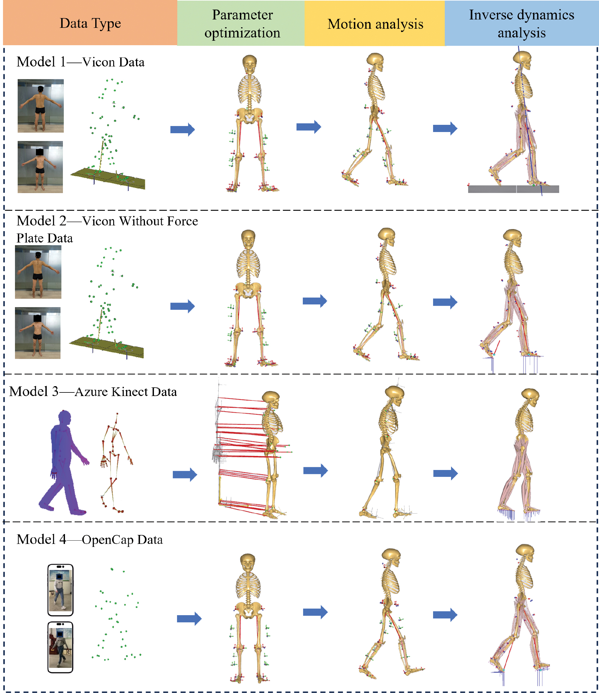
In model 1, the collected gait data were imported into AnyBody in C3D format, and the musculoskeletal model was scaled according to a length-mass-fat scaling law [32], considering the participant’s height, body mass, and gait data, to obtain a musculoskeletal model proportional to the participant’s body segments. Specifically, the static T-pose trial served as a participant-specific standing reference trial to determine the original marker locations on the lower-limb model. To individualize the generic musculoskeletal model, an optimization routine [33] was applied to minimize the differences between the model marker positions and the experimental marker trajectories recorded during the reference trial. During this process, the model parameters, local marker coordinates, and segment lengths were simultaneously optimized with the length-mass-fat scaling law, thereby scaling both body dimensions and muscle strength to the specific participant [10]. Subsequently, muscle recruitment was performed with GRF data as inputs to calculate joint forces in inverse dynamics analysis. Meanwhile, the model calculated the medial and lateral knee contact forces with a previously described method [34].
 (1)
(1)
 (2)
(2)
where KAM represents the knee adduction moment, KCFlateral represents the contact force in the lateral knee compartment, CMAL represents the length of the lateral condyle moment arm, KCFmedial represents the contact force in the medial knee compartment, CMAM represents the length of the medial condyle moment arm, and KCFtotal represents the total knee contact force.
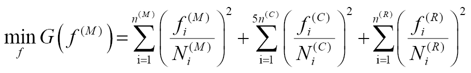
In model 2, GRFs were estimated with the foot-ground contact model [26] instead of being measured by force plates, as in model 1. Specifically, models 1 and 2 used identical kinematic inputs and therefore produced identical joint angle results. In model 2, the GRFs and lower-limb kinetics were predicted simultaneously by integrating a foot-ground contact model. Regarding the foot-ground contact model, 23 contact units were integrated under each foot, each complemented by five artificial muscle actuators. These actuators were designed to produce normal forces perpendicular to the ground and static friction forces in the medial-lateral (ML) and anterior-posterior (AP) directions. GRFs were generated when the distance between the contact unit and the ground was less than 30 mm, and the relative velocity with respect to the ground was less than 0.8 m/s [24]. Muscle recruitment was determined through quadratic optimization, specifically minimizing the sum of squares of muscle, contact, and residual activities to provide forces. The specific formula is as follows [35]:
 (3)
(3)
 (4)
(4)
where ![]() represents the i-th muscle force; n(M) represents the number of muscles;
represents the i-th muscle force; n(M) represents the number of muscles; ![]() represents the muscle strength;
represents the muscle strength; ![]() represents the i-th contact force; n(C) represents the number of contact units;
represents the i-th contact force; n(C) represents the number of contact units; ![]() represents the contact unit strength/N;
represents the contact unit strength/N; ![]() represents the i-th residual force/N;
represents the i-th residual force/N; ![]() represents the number of residual forces;
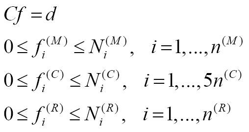
represents the number of residual forces; ![]() represents the residual force strength/N; C represents the matrix of coefficients of the kinetic equilibrium equations; f represents the vector of unknown muscle, contact, and residual forces/N; and d represents the external and inertial forces.
represents the residual force strength/N; C represents the matrix of coefficients of the kinetic equilibrium equations; f represents the vector of unknown muscle, contact, and residual forces/N; and d represents the external and inertial forces.
In model 3, unlike model 1, the musculoskeletal model automatically scaled segment lengths with marker trajectories derived from Azure Kinect data, relying on the distances between joints in the BVH stick-figure skeleton [27]. Specifically, the skeletal joint centers obtained from the Azure Kinect BVH output were mapped to the corresponding joint-center definitions required by the AnyBody model. The inter-joint distances derived from this skeleton were then used for automatic segment scaling, after which the processed TXT data were used to drive the inverse kinematics workflow. Additionally, as in model 2, the GRF data were predicted by the foot-ground contact model because they were not directly measured.
In model 4, two key modifications were introduced relative to model 1. First, the anatomical marker trajectories estimated by OpenCap were exported in TRC format and converted into C3D files for compatibility with the AnyBody workflow. These marker trajectories were matched as closely as possible to the marker set required by the marker-based pipeline and were then used to scale and drive the musculoskeletal model in a manner analogous to that in model 1. Second, in contrast to model 1, the GRFs in model 4 were not measured by force plates but were predicted with the foot-ground contact model for subsequent inverse kinetics and joint contact force estimation.
Lower-limb kinematic and kinetic analyses
The predicted lower-limb joint angles, GRFs, and joint contact forces of model 2, model 3, and model 4 were compared with those of model 1. The lower-limb joint angles included hip flexion-extension (FE), knee FE, and ankle FE, hip adduction-abduction (AA), and internal-external rotation (IE). The GRFs included vertical GRF, AP GRF, and ML GRF. The joint contact forces included hip contact force (HCF), knee contact force (KCF), medial knee contact force (MKCF), lateral knee contact force (LKCF), patellofemoral contact force (PCF), and ankle contact force (ACF).
The calculated kinematic and kinetic data of three trials were averaged for each participant, and joint contact forces and GRFs were simultaneously normalized to body weight (BW). Quantitative analysis of the models was conducted with metrics including mean average deviation (MAD), root mean square error (RMSE), Pearson correlation coefficient (ρ), and Sprague and Geers metrics of magnitude (M), phase (P), and combined (C) error [36]. Specifically, ρ ≤ 0.35 indicated a weak correlation, 0.35 < ρ ≤ 0.67 indicated a moderate correlation, 0.67 < ρ ≤ 0.9 indicated a strong correlation, and ρ > 0.9 indicated an excellent correlation [37].
Results
Lower-limb joint angles
Figure 3 presents a comparison of the lower-limb joint angles computed by models 1, 3, and 4. Models 1 and 2 used identical kinematic inputs to calculate lower-limb joint angles, thus resulting in equivalent outputs. Model 4 aligned more closely to model 1 than did model 3, in terms of both the magnitude and trend of hip, knee, and ankle FE angles. Model 4 demonstrated good agreement with model 1 in terms of hip, knee, and ankle FE angles (Table 1), with ρ exceeding 0.73, RMSE values ranging from 4.04° to 7.66°, M between −0.10 and −0.25, P between 0.08 and 0.25, and C ranging from 0.16 to 0.39. In contrast, model 3 exhibited lower correlation coefficients than model 4 for the hip, knee, and ankle FE angles, with values of 0.94 versus 0.96, 0.47 versus 0.73, and 0.70 versus 0.83, respectively.
Figure 3 Comparison of lower-limb joint angles among model 3, model 4, and model 1.
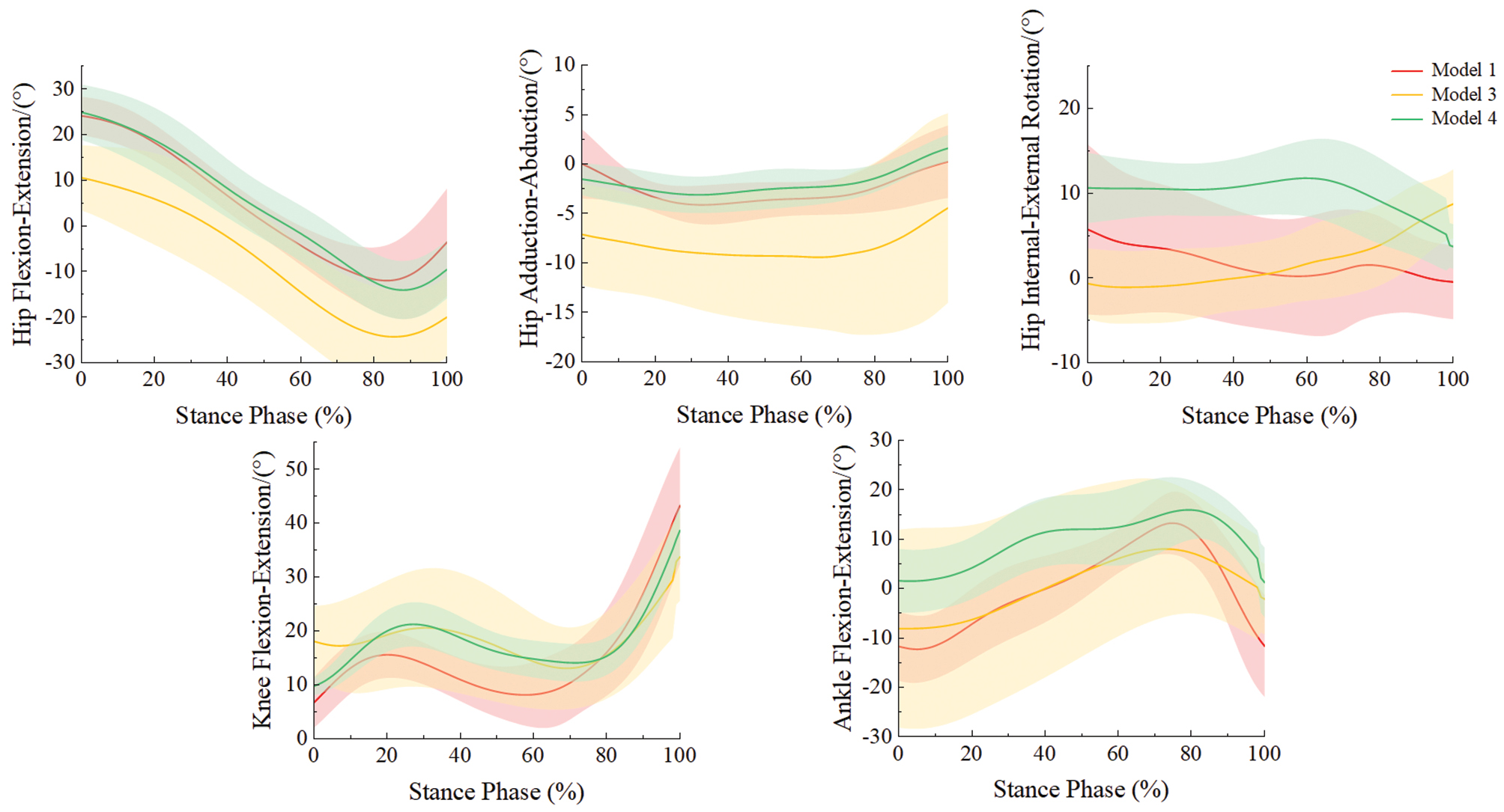
Table 1 Mean Average Deviation (MAD), Root Mean Square Error (RMSE), Pearson Correlation Coefficient (ρ), and Sprague and Geers Metrics of Magnitude (M), Phase (P), and Combined Error (C) of Participants’ Lower-limb Joint Angles, Calculated by Model 3 and Model 4 Compared with Model 1
| MAD/(°) | RMSE/(°) | ρ | M | P | C | ||
|---|---|---|---|---|---|---|---|
| Hip FE | Model 3 | 7.86 | 8.90 | 0.94 | −0.24 | 0.19 | 0.28 |
| Model 4 | 3.50 | 4.04 | 0.96 | −0.10 | 0.08 | 0.16 | |
| Hip AA | Model 3 | 5.78 | 6.50 | 0.42 | −0.72 | 0.16 | 0.64 |
| Model 4 | 1.83 | 2.40 | 0.43 | 0.07 | 0.21 | 0.42 | |
| Hip IE | Model 3 | 6.84 | 7.85 | -0.34 | 0.09 | 0.54 | 0.68 |
| Model 4 | 4.99 | 5.47 | 0.17 | −0.47 | 0.13 | 0.41 | |
| Knee FE | Model 3 | 7.28 | 8.16 | 0.47 | −0.24 | 0.12 | 0.21 |
| Model 4 | 5.63 | 6.66 | 0.73 | −0.25 | 0.08 | 0.25 | |
| Ankle FE | Model 3 | 7.53 | 8.83 | 0.70 | −0.38 | 0.22 | 0.50 |
| Model 4 | 6.61 | 7.66 | 0.83 | −0.22 | 0.25 | 0.39 |
All reported values are means. FE: flexion-extension; AA: adduction-abduction; IE: internal-external rotation.
Ground reaction forces
We subsequently compared GRFs measured by model 1 with those predicted by the foot-ground contact models in models 2, 3, and 4 (Figure 4). The predicted and measured GRFs showed similar magnitudes and trends for both vertical and AP GRFs. Strong consistency was observed for models 2, 3, and 4 for vertical and AP GRFs (Table 2), with ρ between 0.79 and 0.96 and an RMSE less than 0.14 BW.
Figure 4 Comparison of ground reaction forces across all models.
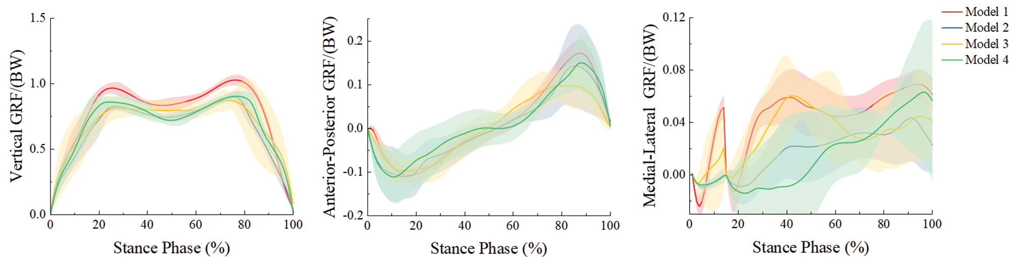
Table 2 Mean Average Deviation (MAD), Root Mean Square Error (RMSE), Pearson Correlation Coefficient (ρ), and Sprague and Geers Metrics of Magnitude (M), Phase (P), and Combined Error (C) of Participants’ Ground Reaction Forces, Calculated by Model 2, Model 3, and Model 4 Compared with Model 1
| MAD/(BW) | RMSE/(BW) | ρ | M | P | C | ||
|---|---|---|---|---|---|---|---|
| Vertical GRF | Model 2 | 0.12 | 0.13 | 0.96 | 0.16 | 0.03 | 0.16 |
| Model 3 | 0.12 | 0.14 | 0.84 | 0.09 | 0.04 | 0.11 | |
| Model 4 | 0.10 | 0.11 | 0.95 | 0.10 | 0.03 | 0.11 | |
| AP GRF | Model 2 | 0.01 | 0.02 | 0.85 | −0.07 | 0.07 | 0.10 |
| Model 3 | 0.03 | 0.04 | 0.87 | 0.05 | 0.14 | 0.24 | |
| Model 4 | 0.03 | 0.03 | 0.79 | −0.08 | 0.12 | 0.14 | |
| ML GRF | Model 2 | 0.02 | 0.02 | 0.64 | 0.51 | 0.13 | 0.57 |
| Model 3 | 0.02 | 0.03 | 0.42 | −0.01 | 0.17 | 0.37 | |
| Model 4 | 0.03 | 0.03 | 0.57 | 0.35 | 0.14 | 0.78 |
All reported values are means. BW: body weight; GRF: ground reaction force; AP: anterior-posterior; ML: medial-lateral.
Joint contact forces
The joint contact forces predicted by models 1, 2, 3, and 4 were compared (Figure 5). Models 1 and 4 produced comparable magnitudes and temporal patterns for HCF, KCF, MKCF, and ACF. Model 4 showed good agreement with model 1 for hip, knee, medial knee, and ankle joint contact forces (Table 3), with ρ ranging from 0.77 to 0.86, RMSE values of 0.26 to 0.90 BW, M of −0.03 to 0.13, P of 0.06 to 0.08, and C of 0.08 to 0.17. For model 3, the ρ for HCF, KCF, MKCF, and ACF was 0.48, 0.45, 0.56, and 0.64, respectively, whereas the corresponding RMSE values were 0.86 BW, 0.69 BW, 0.54 BW, and 1.08 BW, respectively.
Figure 5 Comparison of lower-limb joint contact forces across all models.
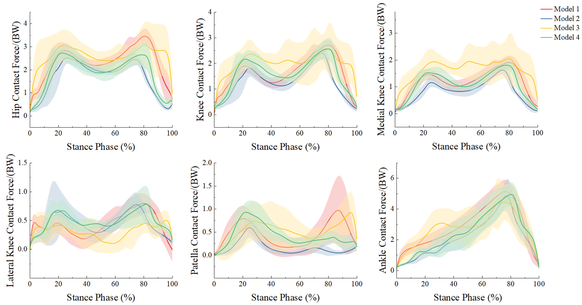
Table 3 Mean Average Deviation (MAD), Root Mean Square Error (RMSE), Pearson Correlation Coefficient (ρ), and Sprague and Geers Metrics of Magnitude (M), Phase (P), and Combined Error (C) of Five Participants’ Lower-limb Joint Contact Forces, Calculated by Model 2, Model 3, and Model 4 Compared with Model 1
| MAD/(BW) | RMSE/(BW) | ρ | M | P | C | ||
|---|---|---|---|---|---|---|---|
| HCF | Model 2 | 0.65 | 0.88 | 0.65 | 0.26 | 0.10 | 0.28 |
| Model 3 | 0.67 | 0.86 | 0.48 | −0.18 | 0.08 | 0.16 | |
| Model 4 | 0.42 | 0.61 | 0.77 | 0.13 | 0.07 | 0.15 | |
| KCF | Model 2 | 0.38 | 0.52 | 0.78 | 0.20 | 0.08 | 0.22 |
| Model 3 | 0.56 | 0.69 | 0.45 | −0.22 | 0.11 | 0.16 | |
| Model 4 | 0.29 | 0.37 | 0.81 | −0.03 | 0.06 | 0.08 | |
| MKCF | Model 2 | 0.34 | 0.42 | 0.82 | 0.32 | 0.08 | 0.34 |
| Model 3 | 0.44 | 0.54 | 0.56 | −0.32 | 0.10 | 0.20 | |
| Model 4 | 0.20 | 0.26 | 0.86 | 0.00 | 0.06 | 0.09 | |
| LKCF | Model 2 | 0.18 | 0.22 | 0.55 | −0.14 | 0.12 | 0.22 |
| Model 3 | 0.24 | 0.30 | 0.06 | 0.12 | 0.21 | 0.30 | |
| Model 4 | 0.20 | 0.24 | 0.48 | −0.22 | 0.12 | 0.25 | |
| PCF | Model 2 | 0.19 | 0.24 | 0.49 | 0.82 | 0.18 | 0.85 |
| Model 3 | 0.27 | 0.37 | 0.27 | −0.33 | 0.19 | 0.44 | |
| Model 4 | 0.20 | 0.26 | 0.43 | −0.25 | 0.14 | 0.32 | |
| ACF | Model 2 | 0.62 | 0.72 | 0.93 | 0.14 | 0.06 | 0.17 |
| Model 3 | 0.89 | 1.08 | 0.64 | −0.08 | 0.09 | 0.16 | |
| Model 4 | 0.76 | 0.90 | 0.84 | 0.00 | 0.08 | 0.17 |
All reported values are means. BW: body weight; HCF: hip contact force; KCF: knee contact force; MKCF: medial knee contact force; LKCF: lateral knee contact force; PCF: patellofemoral contact force; ACF: ankle contact force.
Discussion
This study benchmarked the accuracy of OpenCap and Azure Kinect in reconstructing lower-limb joint kinematics and kinetics against a Vicon-referenced musculoskeletal model. Under the experimental conditions, OpenCap showed closer agreement with the Vicon than Azure Kinect for several sagittal-plane kinematic and kinetic outcomes, thus supporting its preliminary utility in research-oriented and screening-oriented applications.
After extracting and comparing joint angles, we found that Azure Kinect achieved excellent agreement with Vicon for hip and knee FE angles; these findings were consistent with those from a previous study [27], but exhibited larger discrepancies at the ankle than at the hip and knee, probably because of differences in the device’s image-processing tracking algorithms [38]. In contrast, model 4 with the OpenCap achieved good agreement for sagittal-plane hip, knee, and ankle joint angles; these observations were consistent with findings reported by Uhlrich et al. [21]. Notably, models 3 and 4 exhibited larger discrepancies with respect to model 1 in hip AA and IE rotation angles, probably because markerless 3D motion data are inferred from 2D video pose estimation, in which errors in pelvis and hip joint localization can influence rotational angle estimates [21]. In addition, inaccuracy in mapping video-derived joint centers or anatomical markers to the anatomical definitions required by the AnyBody model might have further contributed to these errors, particularly for rotational degrees of freedom that are highly sensitive to small spatial misalignments.
Because Azure Kinect and OpenCap were unable to directly acquire GRFs, models 3 and 4 incorporated a foot-ground contact model [26]. The comparison between models 2 and 1 further validated the foot-ground contact model’s ability to predict GRFs. When applied to models 3 and 4, the foot-ground contact model also yielded vertical and AP GRFs generally consistent with those of model 1. In contrast, models 2, 3, and 4 predicted ML GRF with lower accuracy. The foot-ground contact model predicts GRFs with kinematic activation thresholds [26, 35]. Minor tracking noise from markerless inputs can propagate directly into these threshold calculations, thereby disproportionately affecting lower-magnitude variables such as ML GRFs [39]. Furthermore, because GRFs and joint contact forces are simultaneously resolved via a quadratic muscle recruitment algorithm [24, 35], slight dynamic inconsistencies from markerless data force the optimization solver to alter muscle recruitment and contact forces to balance the equations. This global optimization trade-off fundamentally explains the coupled deviations in both ML GRF and joint contact force predictions [24, 35]. Future studies may consider incorporating additional foot kinetic parameters or improved contact modeling strategies to enhance the prediction accuracy of ML GRFs.
Compared with model 1, model 4 showed good agreement in HCF, total KCF, MKCF, and ACF, whereas the correlations for LKCF and PCF were weaker, possibly because of errors in predicted ML GRFs [35] and discrepancies between video-derived marker positions and Vicon marker placements [21]. In addition, model 4 exhibited relatively larger RMSE than model 1 for hip and ankle joint contact forces; however, notably, model 2, which shared identical kinematic inputs with model 1, showed similarly large RMSE values, probably because of differences in muscle recruitment strategies between the models [35]. Similar limitations were observed for model 3; however, OpenCap showed overall closer agreement with model 1 than Azure Kinect for the prediction of joint contact forces.
In interpreting these results within a clinical context, the physiological and clinical significance of the observed errors must be carefully considered. Regarding kinematics, an error threshold below 5° in joint angles is generally considered acceptable for clinical interpretation in traditional marker-based clinical gait analysis [40, 41]. The observed RMSE of 4.04° to 7.66° specifically for the OpenCap demonstrated preliminary clinical potential but partially exceeded this strict diagnostic tolerance. Furthermore, this error magnitude overlapped with the minimal clinically important difference established for certain lower-limb pathologies [42], such as the 6.81° to 8.48° [43] improvement required for sagittal knee range of motion in patients with chronic stroke. Consequently, although OpenCap showed closer agreement with the Vicon than Azure Kinect in our study, it might still lack the sensitivity to distinguish subtle, true clinical improvements from inherent measurement noise, and consequently fail to overcome the minimal detectable change required for precision diagnostics.
Regarding kinetics, the observed errors in joint contact forces (0.26 to 0.90 BW) predicted by the OpenCap were relatively substantial. Recent literature [43] has highlighted that kinetic measurement errors of this magnitude might not yet accurately detect clinically meaningful changes in localized joint loading. Therefore, although OpenCap provides a highly accessible markerless workflow, its predicted kinetic parameters might not satisfy the strict accuracy tolerances required for high-precision surgical planning or the mechanical evaluation of implant wear. Nevertheless, OpenCap remains highly applicable for the macroscopic, longitudinal monitoring of rehabilitation interventions aimed at optimizing gait mechanics and reducing overall joint loading [44].
This proof-of-concept study has several limitations. First, the study’s inclusion of five healthy young male participants constrained the statistical power and generalizability of the findings. Although this design was sufficient for technical validation of the simulation framework, future studies should expand the sample size and include diverse populations (older adults, different BMI categories, and patients with musculoskeletal disorders) to establish the clinical applicability and robustness of the markerless motion capture workflow. Second, the validation was limited to self-selected speed walking; future studies should extend the framework to more demanding activities, such as stair negotiation, sit-to-stand, squatting, and running. Third, because both Azure Kinect and OpenCap were tested only in a dual-camera configuration, the present findings should be interpreted as specific to this setup. Future work should systematically compare different camera configurations to quantify the effects of additional viewpoints on simulation accuracy. Finally, all data were collected in a highly controlled laboratory environment, and further validation is needed under more variable real-world conditions, including changes in lighting, background, and clothing.
Conclusions
This study assessed the accuracy of the Azure Kinect and OpenCap for estimating lower-limb biomechanics by benchmarking them against the Vicon. Compared with the Azure Kinect, the musculoskeletal model with OpenCap data demonstrated closer agreement with the Vicon (ρρ > 0.7) in estimating lower-limb joint kinematics (sagittal-plane joint angles) and joint contact forces (HCF, KCF, MKCF, and ACF). Therefore, under the study conditions, specifically including a dual-camera setup, self-selected walking speed, and a controlled laboratory environment, OpenCap preliminarily showed accuracy as a potential alternative to Vicon for selected lower-limb biomechanical outcomes. However, given the current sample size and task scope, the present utility of this system is interpreted as being primarily for research settings or initial screening rather than for high-precision clinical diagnosis or surgical decision-making.
Data availability statement
The datasets generated and/or analyzed during the current study are not publicly available, because of privacy issues. However, data will be made available on formal request to the corresponding authors.
Ethics statement
The study was approved by the Ethics Committee of Honghui Hospital (No. 202407002), and all participants provided written informed consent before data collection.
Author contributions
Qiang Gao: Original Draft, Review and Editing, Methodology, Visualization, Validation, Investigation, Formal Analysis. Yan Wang: Original Draft, Methodology, Visualization, Validation. Xiaodong Dang: Review and Editing, Methodology, Visualization, Validation, Formal Analysis. Pingping Wei and Weijie Zhang: Resources. Zhifeng Zhang and Jing Zhang: Funding Acquisition. Yangkang Zeng: Review and Editing. Zhenxian Chen: Review and Editing, Funding Acquisition. Yinghu Peng: Review and Editing, Funding Acquisition.
Acknowledgments
This work was supported by the National Natural Science Foundation of China under grant numbers 12202074, 12302421, and 12572367; the Shenzhen Science and Technology Innovation Program under grant number KQTD20210811090217009; the Shenzhen Science and Technology Program under grant number JCYJ20240813154923031; the Guangdong Basic and Applied Basic Research Foundation under grant number 2025A1515011989; and the Nanshan District Health Science and Technology Program under grant number NS2024008. We express our gratitude to Honghui Hospital and the State Key Laboratory for Manufacturing System Engineering in Xi’an Jiaotong University for invaluable consultation and the provision of instrumental resources that supported this work. The Graphical abstract, Figure 1, and Figure 2 were created with PowerPoint. Figure 3, 4, and 5 were created with Origin.
Conflicts of interest
The authors declare that there are no conflicts of interest.
Graphical abstract
Highlights
- The performance of RGB-D camera-based and smartphone-based motion capture systems was evaluated.
- Lower-limb joint angles, joint contact forces, and ground reaction forces were compared between marker and markerless-based methods.
- The Smartphone-based OpenCap method might potentially offer higher accuracy than the Azure Kinect method.
- The markerless motion capture system can be used in lower-limb musculoskeletal simulation research.
In brief
This proof-of-concept study was aimed at developing a single lower-limb musculoskeletal model driven simultaneously by two markerless motion capture inputs (Azure Kinect and OpenCap), and benchmarking the resulting joint angles, ground reaction forces, and joint contact forces against synchronous Vicon recordings. The smartphone-based OpenCap system, when integrated with a foot-ground contact model, accurately predicted lower-limb kinematics and joint contact forces during walking. OpenCap therefore offers a cost-effective and portable alternative to traditional marker-based motion capture for biomechanical research and initial clinical screening.
References
- Brockett CL, Chapman GJ. Biomechanics of the ankle. Orthop Trauma 2016;30(3):232-8. [PMID: 27594929 DOI: 10.1016/j.mporth.2016.04.015]
- Yang C, Wei L, Huang X, Tu L, Xu Y, et al. Comparison of lower limb kinematic and kinetic estimation during athlete jumping between markerless and marker-based motion capture systems. Sci Rep 2025;15(1):18552. [PMID: 40425708 DOI: 10.1038/s41598-025-02739-9]
- Aharonson V, Seedat N, Israeli-Korn S, Hassin-Baer S, Postema M, et al. Automated stage discrimination of Parkinson’s disease. BIOI 2020;1(2):55-63. [DOI: 10.15212/bioi-2020-0006]
- Xu D, Zhou H, Quan W, Ma X, Chon TE, et al. New insights optimize landing strategies to reduce lower limb injury risk. Cyborg Bionic Syst 2024;5:0126. [PMID: 38778877 DOI: 10.34133/cbsystems.0126]
- van der Veen SM, Bordeleau M, Pidcoe PE, France CR, Thomas JS. Agreement analysis between Vive and Vicon systems to monitor lumbar postural changes. Sensors 2019;19(17):3632. [PMID: 31438520 DOI: 10.3390/s19173632]
- Fregly BJ, Besier TF, Lloyd DG, Delp SL, Banks SA, et al. Grand challenge competition to predict in vivo knee loads. J Orthop Res 2012;30(4):503-13. [PMID: 22161745 DOI: 10.1002/jor.22023]
- Illés T, Somoskeöy S. The EOS™ imaging system and its uses in daily orthopaedic practice. Int Orthop (SICOT) 2012;36(7):1325-31. [PMID: 22371113 DOI: 10.1007/s00264-012-1512-y]
- Kernkamp WA, Van De Velde SK, Hosseini A, Tsai TY, Li JS, et al. In vivo anterolateral ligament length change in the healthy knee during functional activities—a combined magnetic resonance and dual fluoroscopic imaging analysis. Arthroscopy 2017;33(1):133-9. [PMID: 27663034 DOI: 10.1016/j.arthro.2016.07.008]
- Marra MA, Vanheule V, Fluit R, Koopman BHFJM, Rasmussen J, et al. A subject-specific musculoskeletal modeling framework to predict in vivo mechanics of total knee arthroplasty. J Biomech Eng 2015;137(2):020904. [PMID: 25429519 DOI: 10.1115/1.4029258]
- Chen Z, Zhang Z, Wang L, Li D, Zhang Y, et al. Evaluation of a subject-specific musculoskeletal modelling framework for load prediction in total knee arthroplasty. Med Eng Phys 2016;38(8):708-16. [PMID: 27245748 DOI: 10.1016/j.medengphy.2016.04.010]
- Xu D, Zhou H, Jie T, Zhou Z, Yuan Y, et al. Data-driven deep learning for predicting ligament fatigue failure risk mechanisms. Int J Mech Sci 2025;301:110519. [DOI: 10.1016/j.ijmecsci.2025.110519]
- Kakavand R, Ahmadi R, Parsaei A, Brent Edwards W, Komeili A. Comparison of kinematics and kinetics between OpenCap and a marker-based motion capture system in cycling. Comput Biol Med 2025;192(Pt A):110295. [PMID: 40311466 DOI: 10.1016/j.compbiomed.2025.110295]
- Calderone J, Outerleys J, Diaz Dilernia F, Mann S, Wood G, et al. Measuring static and dynamic lower limb alignment in patients with advanced knee osteoarthritis using markerless motion capture. Gait Posture 2025;119:157-62. [PMID: 40101546 DOI: 10.1016/j.gaitpost.2025.02.022]
- Curreli C, Di Puccio F, Davico G, Modenese L, Viceconti M. Using musculoskeletal models to estimate in vivo total knee replacement kinematics and loads: effect of differences between models. Front Bioeng Biotechnol 2021;9:703508. [PMID: 34395407 DOI: 10.3389/fbioe.2021.703508]
- Topley M, Richards JG. A comparison of currently available optoelectronic motion capture systems. J Biomech 2020;106:109820. [PMID: 32517978 DOI: 10.1016/j.jbiomech.2020.109820]
- Napoli A, Glass S, Ward C, Tucker C, Obeid I. Performance analysis of a generalized motion capture system using microsoft kinect 2.0. Biomed Signal Process Control 2017;38:265-80. [DOI: 10.1016/j.bspc.2017.06.006]
- Eltoukhy M, Kuenze C, Andersen MS, Oh J, Signorile J. Prediction of ground reaction forces for Parkinson’s disease patients using a kinect-driven musculoskeletal gait analysis model. Med Eng Phys 2017;50:75-82. [PMID: 29102274 DOI: 10.1016/j.medengphy.2017.10.004]
- Albert JA, Owolabi V, Gebel A, Brahms CM, Granacher U, et al. Evaluation of the pose tracking performance of the Azure Kinect and Kinect v2 for gait analysis in comparison with a gold standard: a pilot study. Sensors 2020;20(18):5104. [PMID: 32911651 DOI: 10.3390/s20185104]
- Skals S, Rasmussen KP, Bendtsen KM, Yang J, Andersen MS. A musculoskeletal model driven by dual Microsoft Kinect Sensor data. Multibody Syst Dyn 2017;41:297-316. [DOI: 10.1007/s11044-017-9573-8]
- Asadi F, Arjmand N. Marker-less versus marker-based driven musculoskeletal models of the spine during static load-handling activities. J Biomech 2020;112:110043. [PMID: 32950760 DOI: 10.1016/j.jbiomech.2020.110043]
- Uhlrich SD, Falisse A, Kidziński Ł, Muccini J, Ko M, et al. OpenCap: human movement dynamics from smartphone videos. PLoS Comput Biol 2023;19(10):e1011462. [PMID: 37856442 DOI: 10.1371/journal.pcbi.1011462]
- Cerfoglio S, Ferraris C, Vismara L, Amprimo G, Priano L, et al. Kinect-based assessment of lower limbs during gait in post-stroke hemiplegic patients: a narrative review. Sensors 2022;22(13):4910. [PMID: 35808426 DOI: 10.3390/s22134910]
- Lima Y, Collings T, Hall M, Bourne M, Diamond L. Assessing lower-limb kinematics via OpenCap during dynamic tasks relevant to anterior cruciate ligament injury: a validity study. J Sci Med Sport 2023;26(Suppl 2):S105. [DOI: 10.1016/j.jsams.2023.08.123]
- Peng Y, Zhang Z, Gao Y, Chen Z, Xin H, et al. Concurrent prediction of ground reaction forces and moments and tibiofemoral contact forces during walking using musculoskeletal modelling. Med Eng Phys 2018;52:31-40. [PMID: 29269224 DOI: 10.1016/j.medengphy.2017.11.008]
- Jung Y, Jung M, Lee K, Koo S. Ground reaction force estimation using an insole-type pressure mat and joint kinematics during walking. J Biomech 2014;47(11):2693-9. [PMID: 24917473 DOI: 10.1016/j.jbiomech.2014.05.007]
- Fluit R, Andersen MS, Kolk S, Verdonschot N, Koopman HFJM. Prediction of ground reaction forces and moments during various activities of daily living. J Biomech 2014;47(10):2321-9. [PMID: 24835471 DOI: 10.1016/j.jbiomech.2014.04.030]
- Ripic Z, Kuenze C, Andersen MS, Theodorakos I, Signorile J, et al. Ground reaction force and joint moment estimation during gait using an Azure Kinect-driven musculoskeletal modeling approach. Gait Posture 2022;95:49-55. [PMID: 35428024 DOI: 10.1016/j.gaitpost.2022.04.005]
- Horsak B, Eichmann A, Lauer K, Prock K, Krondorfer P, et al. Concurrent validity of smartphone-based markerless motion capturing to quantify lower-limb joint kinematics in healthy and pathological gait. J Biomech 2023;159:111801. [PMID: 37738945 DOI: 10.1016/j.jbiomech.2023.111801]
- Peng Y, Wang W, Wang L, Zhou H, Chen Z, et al. Smartphone videos-driven musculoskeletal multibody dynamics modelling workflow to estimate the lower limb joint contact forces and ground reaction forces. Med Biol Eng Comput 2024;62(12):3841-53. [PMID: 39046692 DOI: 10.1007/s11517-024-03171-3]
- Cao Z, Hidalgo G, Simon T, Wei SE, Sheikh Y. OpenPose: realtime multi-person 2D pose estimation using part affinity fields. IEEE Trans Pattern Anal Mach Intell 2021;43(1):172-86. [PMID: 31331883 DOI: 10.1109/TPAMI.2019.2929257]
- Michaud B, Begon M. ezc3d: an easy C3D file I/O cross-platform solution for C++, Python and MATLAB. J Open Source Softw 2021;6(58):2911. [DOI: 10.21105/joss.02911]
- Pellikaan P, Van Der Krogt MM, Carbone V, Fluit R, Vigneron LM, et al. Evaluation of a morphing based method to estimate muscle attachment sites of the lower extremity. J Biomech 2014;47(5):1144-50. [PMID: 24418197 DOI: 10.1016/j.jbiomech.2013.12.010]
- Andersen MS, Damsgaard M, MacWilliams B, Rasmussen J. A computationally efficient optimisation-based method for parameter identification of kinematically determinate and over-determinate biomechanical systems. Comput Methods Biomech Biomed Engin 2010;13(2):171-83. [PMID: 19693717 DOI: 10.1080/10255840903067080]
- Richards RE, Andersen MS, Harlaar J, Van Den Noort JC. Relationship between knee joint contact forces and external knee joint moments in patients with medial knee osteoarthritis: effects of gait modifications. Osteoarthritis Cartilage 2018;26(9):1203-14. [PMID: 29715509 DOI: 10.1016/j.joca.2018.04.011]
- Skals S, Jung MK, Damsgaard M, Andersen MS. Prediction of ground reaction forces and moments during sports-related movements. Multibody Syst Dyn 2017;39:175-95. [DOI: 10.1007/s11044-016-9537-4]
- Sprague MA, Geers TL. Spectral elements and field separation for an acoustic fluid subject to cavitation. J Comput Phys 2003;184(1):149-62. [DOI: 10.1016/S0021-9991(02)00024-4]
- Taylor R. Interpretation of the correlation coefficient: a basic review. J Diagn Med Sonogr 1990;6(1):35-9. [DOI: 10.1177/875647939000600106]
- Wang Y, Sun J, Li J, Zhao D. Gait recognition based on 3D skeleton joints captured by kinect. In: 2016 IEEE International Conference on Image Processing (ICIP), Phoenix, AZ, USA. IEEE; 2016. pp. 3151-5. [DOI: 10.1109/ICIP.2016.7532940]
- Kitaoka HB, Crevoisier XM, Hansen D, Katajarvi B, Harbst K, et al. Foot and ankle kinematics and ground reaction forces during ambulation. Foot Ankle Int 2006;27(10):808-13. [PMID: 17054883 DOI: 10.1177/107110070602701010]
- Alalem N, Gasparutto X, Rose-Dulcina K, DiGiovanni P, Hannouche D, et al. Validity of a single inertial measurement unit to measure hip range of motion during gait in patients undergoing total hip arthroplasty. Sensors 2025;25(1):3363. [PMID: 40968908 DOI: 10.3390/s25113363]
- McGinley JL, Baker R, Wolfe R, Morris ME. The reliability of three-dimensional kinematic gait measurements: a systematic review. Gait Posture 2009;29(3):360-9. [PMID: 19013070 DOI: 10.1016/j.gaitpost.2008.09.003]
- Guzik A, Drużbicki M, Wolan-Nieroda A, Turolla A, Kiper P. Estimating minimal clinically important differences for knee range of motion after stroke. J Clin Med 2020;9(10):3305. [PMID: 33076214 DOI: 10.3390/jcm9103305]
- Xu J, Wen Z, Augustine S, Sharir R, De Bleecker C, et al. Inter-session reliability of markerless lower extremity joint kinematics and kinetics for return-to-sport screening tasks. J Sports Sci 2025;43(21):2576-90. [PMID: 40757785 DOI: 10.1080/02640414.2025.2541490]
- Kamal KC, Kamal AM, Kamal D, Fugaru O, Matei D, et al. Gait analysis as a measure of physical performance in older adults with bilateral knee osteoarthritis. Medicina 2025;61(12):2118. [PMID: 41470120 DOI: 10.3390/medicina61122118]